Homemade Digital Voltmeter Circuit Diagram. The 8051 microcontroller is a widely used microcontroller, which is. Web this simple digital voltmeter circuit diagram is a saving, easy to use because it is smaller than a typical circuit, i believe that after i presented this circuit.
Led Digital Voltmeter Circuit Diagram Pdf Wiring View And Schematics from www.wiringview.co
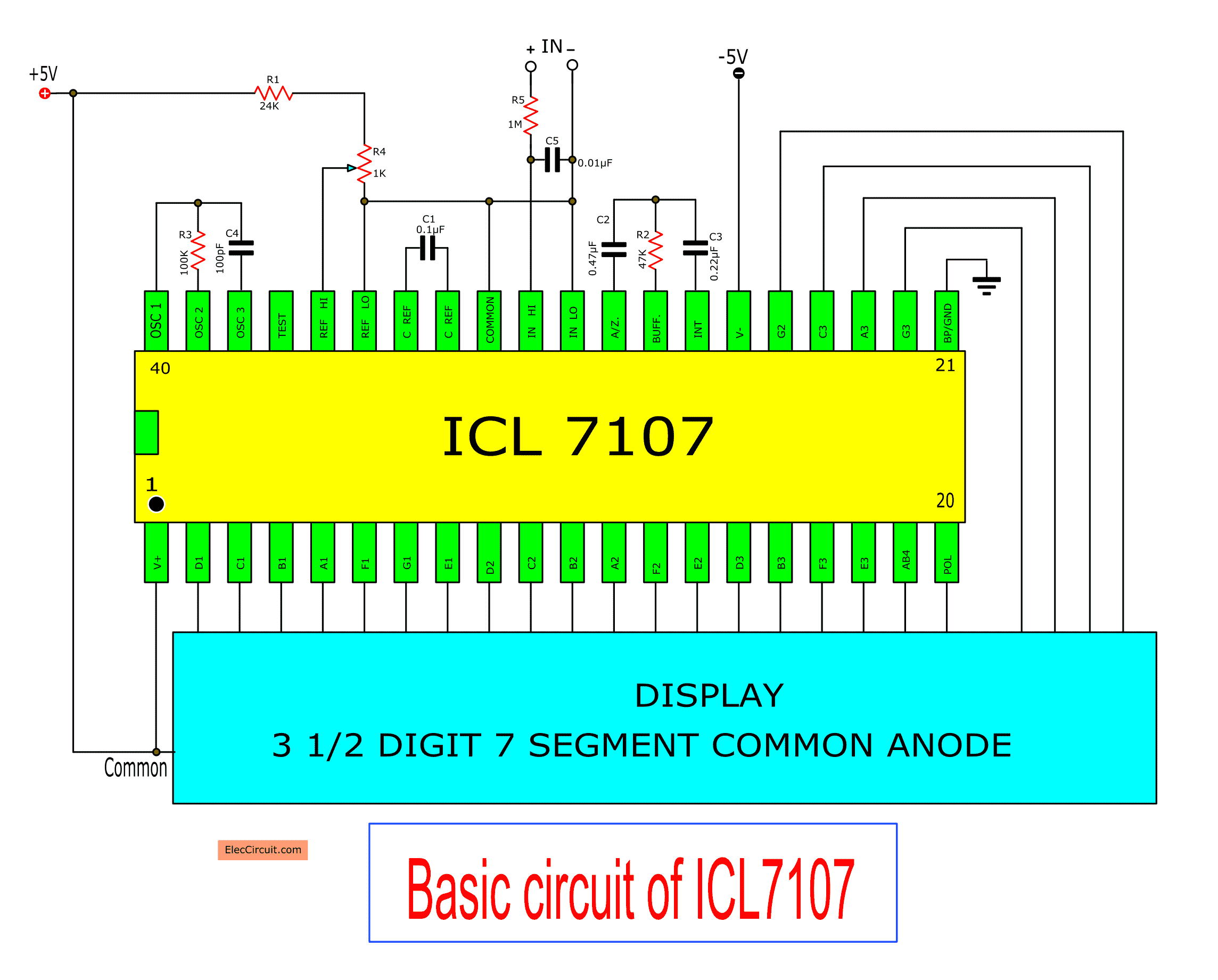
Web an rms detector for a wideband voltmeter—design and operation; Web the rectangles represent resistors and transistors, the circles represent capacitors, and the lines represent the wires connecting the components. Web now let us discuss how does a digital voltmeter work and working principle of digital voltmeters and block diagram.
Digital Voltmeters A Digital Voltmeter ( Dvm ).
Circuit diagram of the digital. Web now let us discuss how does a digital voltmeter work and working principle of digital voltmeters and block diagram. Web how it works the circuit consists of two resistors, one lcd display and an arduino which is brain of the digital voltmeter.
The Two Resistor Acts As Voltage Divider,.
Web an rms detector for a wideband voltmeter—design and operation; Web led display digital voltmeter circuit diagrams schematics electronic projects. Web this simple digital voltmeter circuit diagram is a saving, easy to use because it is smaller than a typical circuit, i believe that after i presented this circuit.
Make A Digital Voltmeter Using An Arduino;
The simplest digital voltmeter with avr. The 8051 microcontroller is a widely used microcontroller, which is. Web in this article, we will discuss the implementation of a digital voltmeter using 8051 microcontroller.
Web The Rectangles Represent Resistors And Transistors, The Circles Represent Capacitors, And The Lines Represent The Wires Connecting The Components.